


Sixty Four
Panneau Arrière
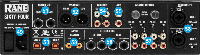
- POWER. Connect the supplied universal AC cord. Power on the unit after all the necessary connections are done.
- USB A/B. These USB connections send and receive audio and control information from the connected computers. See more details in Back to Back.
- BOOTH OUT Use a pair of balanced ¼“ TRS jacks to connect the unit with your secondary output (e.g. for monitor). The level of this output is controlled by the BOOTH knob at the top panel
- MAIN OUT. Connect your amplifier using a pair of balanced XLR jacks. The level of this output is controlled by the MAIN knob at the top panel
- S/PDIF. S/PDIF Input and Output. Used to digitally link mixers without converting to analog.
- SESSION IN/OUT. Use standard RCA cables for the connections. The level of both Input and Output are controlled by the SESSION IN and OUT knobs at the top panel. These can be used to for connecting two mixer together (chain)
- AUX. Stereo unbalanced Auxiliary Input. Can be selected as input source to any of the 4 Decks.
- FLEXFX LOOP Use balanced pairs of ¼” TS jacks for the SEND and RETURN Inputs. For a mono FLEXFX Send use the Left Output. The FlexFX output is normally used along with the FLEXFX LOOP RETURN input to connect outboard effects.
- ANALOG INPUTS. Four Phono/CD inputs are provided by RCA jacks (one for each Deck/mixer channel). These may be set for PH or CD using the rear panel slide switches. Analogue inputs may be selected as Timecode Inputs. See Timecode (DVS).
Set any unused inputs to CD. Connect your turntable ground wires to the PHONO GOUND posts on the rear when using PH inputs. - MIC INPUTS Connect your microphones using a XLR 3-pin plug, a balanced ¼” TRS plug or unbalanced TS plug. MIC1 offers phantom power. MIC2 may be set as Microphone or Line Input using the MIC-LINE switch on the rear panel. Set this to Line when connecting a wireless receiver.
Note: The Main, Booth and Session outputs arrive from the same “Main Mix” signal. Each one of them has its own LEVEL control at the top panel. Because all signals are identical, users may use any of these outputs as the “Main” output if a different cable type is required for system connection.